
Understanding and Troubleshooting the SA-200 DC Generator
If you want to understand your Lincoln SA-200 welding machine, you need a basic understanding of the DC generator. Your SA-200 is really two DC generators that work in tandem.
The first generator is the exciter (the nose that sticks out the front of the machine). This exciter is actually a 2 kW (kilowatt) DC generator which provides a DC current that is adjusted to control the welder output. The exciter also provides an aux. 115 volts DC for accessories.
The second generator is the welding generator. This generator produces a regulated constant current output that produces the wonderful arc that welders love. Both generators operate on the same principals; one is just much larger!
In this article, we are only going to discuss the exciter generator and exciter control circuit. This circuit is very simple to understand, troubleshoot, and repair.
Keep reading, or jump ahead to a specific section of this guide:
Exciter Parts Location and Definitions:
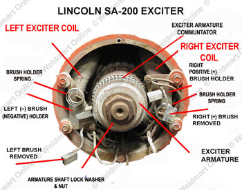
The graphic above is of a standard Lincoln SA-200 exciter, with the end cap removed. Facing the machine from the front, note the location and name of each item:
- The right-hand brush holder is the positive spring-loaded brush holder.
- The left-hand brush holder is the negative spring-loaded brush holder.
- Behind the right brush holder is the right exciter coil.
- Behind the left brush holder is the left exciter coil.
- The exciter armature is held onto the armature shaft by a nut secured by a lock washer.
- Each brush holder is flanked by a brush holder spring.
How the System Works:
The exciter coils and the pole pieces form electromagnets when DC current flows through the exciter coils. The magnetic fields produced by the exciter coils are broken by the windings on the exciter armature, producing approximately 115 volts DC at full RPM. The faster the engine turns, the more voltage the exciter produces. At welding speed (1550 RPM), the exciter voltage should be approximately 115 volts DC: positive on the right brush holder, negative on the left brush holder.
The system is a series-wound compound generator, with an additional shunt coil across the exciter armature. The fine-current control (“heat control”) rheostat varies the exciter voltage that is applied to the main stator shunt coils; this variable voltage controls the output current (heat) of the arc.
Troubleshooting the Exciter Field Coils
By studying the wiring diagram below, you can see that there are two halves of the exciter circuit, designated by the red line with arrows on each end. (This red line is not part of the circuit, just a visual aid.)
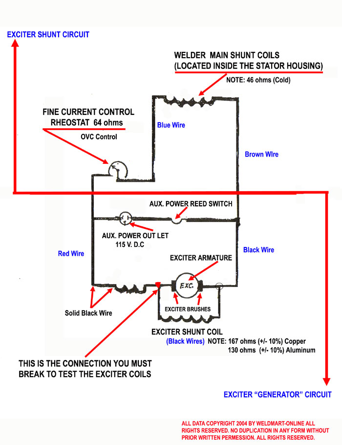
The "exciter generator" produces 115 volts DC that is fed to the auxiliary power outlet and to the main exciter shunt coils. This DC current is varied by the fine-current control rheostat (think of it as a valve), then fed into the main exciter shunt coils. This controls the strength of the magnetic field, which controls the amount of welding current that is available. If there is a fault in either circuit, the machine will not weld.
If the failure is in the “exciter shunt circuit,” the generator can still produce power. This can be verified by checking the auxiliary with a meter, light, or a grinder. If you can "grind," but not weld, check the main exciter shunt coils.
The exciter shunt coils in the SA-200 are simple to diagnose and replace. Get more information on Weldmart-Onlinereplacement exciter coils, which come with a ten-year warranty.
Weldmart-OnlineReplacement Exciter Coils
Troubleshooting the Main Exciter Shunt Coils
NOTE: All electrical troubleshooting measurements must be made with the engine OFF (not running)!
-
Before you make any measurements, your exciter should look like the image below.
- Reach under the exciter armature and locate the black and blue leads, the wires should be connected with a “butt” splice or bolted together. (If you find a splice, the coils have never been checked for continuity.) If they are spliced or connected with bolt and nut, you must break these wires apart. When you separate them, you can check the separate coils.
- To check the exciter field coils, remove both exciter brushes from their holders and make sure they do not touch anything while making measurements. With you VOM, on the lowest resistance scale you can use, check resistance between the RIGHT brush lead to each of the separated wires. If the coil is good, one wire will show resistance, the other will not-this is normal. The resistance should be approximately 130 to 170 ohms, + or – 10%. If you get no resistance, go to the next higher range. Make sure you are not touching the leads with your fingers: you could be reading the resistance of your body.
- Next check the resistance from the each coil lead to the outside terminal (it may have a red wire attached) of the fine current control rheostat. One of the wires will show continuity between the lead and the rheostat. Both measurements should be identical.
- If either measurement shows very high resistance, or an “open coil” infinite resistance, or a very low resistance (less than 100 ohms), then the coils must be replaced.
- If the coils check out OK, you should suspect the exciter armature.
Troubleshooting the Exciter Armature:
You will occasionally find a defective exciter armature; here is what to look for with the most common problems.
- Look for burnt or blackened commutator bars before you check any further. Clean the commutator with a commutator cleaning stone. It is not normal for the brushes to deposit enough carbon powder to contaminate the commutator.
Note: a properly maintained commutator should be the color of used burnished penny.
- Inspect the windings for any burnt insulation, broken wires, or damaged commutator bars. Armatures have two problems: a winding that is shorted to the armature shaft or broken (open) windings.
NOTE: If a BRIGHT GREEN SPARK is seen when the unit is running, that is a sign of a shorted (to ground) armature winding.
- Check for an armature shorted to ground with your VOM set to the HIGHEST resistance range. Place one lead on a clean spot on the armature shaft (if you have any doubt, clean a spot with fine emory paper or a file). With the other lead, check each commutator bar. Don’t miss any: if you have any doubts, check them ALL again.
If you find any resistance reading, you need to replace the armature with a new or rebuilt one. If you do not find any shorts to ground, it could still be defective. Remove the armature and take it to a motor repair shop and have it tested on a “growler” (they will know what to do). The “growler” test is the “gold standard” for testing an armature -- it is worth paying for the test! If the armature is defective, call Weldmart; we have rebuilt armatures.
Other Exciter Armature Problems:
- A high bar means just that: one of the commutator bars has come loose and is sticking up. It could be just a few thousands of an inch, but that can be enough to make the brushes jump, and you will see excessive sparking. If you find this problem, take it to you favorite motor shop: sometimes it can be repaired and sometimes not.
- Loose bar: Yes, sometimes a commutator segment bar can break loose. Back to the motor shop.
- Commutator out of round: This can be caused by a bent armature shaft. Have the exciter checked for out of roundness. The rule is at 1500 rpm is (+ or -) .020’.
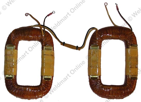
Trick of the Trade: How to Install New Exciter Coils, Quickly and Easily with No Guess-Work
- Do not start until you have your new set of coils in hand.
- Remove the original coils. There are two bolts holding each iron exciter pole piece in place, two on the right side and two on the left!
- You do not have to remove the exciter generator to replace the exciter coils.
- Pull the coils and iron pole pieces out together and lay them on a flat surface. Do not disconnect any wires yet!
- Remove the iron pole pieces, and clean them up: normally a good once-over with a wire wheel will do the trick. They do not have to be painted.
- Lay the coils on top of the original coils and match the wires coming off both sides and the middle. You have your wiring diagram in front of you!
- Insert the iron pole pieces into the center of the coils.
- Before you install the coils and pole pieces, clean out the housing: just knock off the rust and rats' nests. It wouldn't hurt to coat the pole pieces with a light coat of grease where they touch the exciter housing. Wire-brush the threads of the mounting bolts; a bit of grease or "Never-Seize" on the threads would not hurt either. Snug the bolts; they do not have to be super tight!
- Attach the wires one at a time using the original coils as a guide; it's obvious where each wire connects.
- We call this "Exciter Coil Replacement for the Complete Idiot!" (Our boss named it after himself.) This process always works for us!
Flashing the Field:
The exciter field coils are held in place with solid iron “pole pieces.” The special pieces of iron do more than just hold the exciter coils in place. They retain a small amount of residual magnetism--just a bit--in order to provide “self-excitation,” so the exciter will start generating current from a dead start. The pole pieces can loose their magnetism as the unit sits idle for a long period of time, and there is no easy test to detect the loss.
When the exciter field coils, the brushes, and the exciter armature all check out, the only thing left to do is “flash the field.” This is normally done with a 12-volt car battery.
Here is what you need to do:
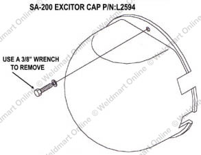
- Remove the exciter dust cover. It is held on with two 1/4 20 bolts; you will need a 3/8” wrench.
- Refer to the diagram below:
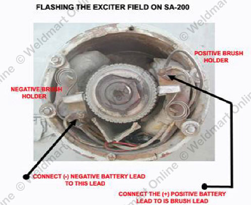
- Connect jumper wires first to the battery, then to the exciter brush terminals. You are likely going to cause a spark: batteries may have pockets of internal hydrogen gas. BATTERIES CAN AND WILL BLOW UP IF GIVEN A LARGE ENOUGH SPARK! (Remember the Hindenburg?-it was full of Hydrogen; enough said).
- Start the engine and make sure it is running at its slow speed (1000 RPM).
- Connect the positive (+) lead to the RIGHT brush lead terminal.
- Touch the negative (-) lead to the LEFT brush lead terminal. You will generate a strong spark. Hold the leads on the terminal for approximately two seconds; there will be a strong spark!
The field poles have been “flashed.” The unit should excite. If successful, you will be able to use the aux. If the unit will not weld, you should check out the exciter shunt coils (see the next section).
Troubleshooting the Exciter Shunt Circuit
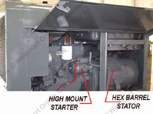
The welding machine will not weld: you can run a grinder off the auxiliary power outlet, and it may or may not idle up on auxiliary demand, but it will not strike an arc. If you can drag the rod and get a small "sparkle" off the electrode, this is a classic sign that one of the exciter shunt coils has failed. This failure is very common in "Hex-Barrel" Lincoln welders!
Note: Code numbers 7276 through 9530 on the SA-200, code numbers 7827 through 9605 on the SA-250, and all Classic 1, 2, and 3 models are "Hex-Barrel" machines.
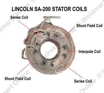
The exciter coils are deep inside the stator housing. In my experience, I have never seen the field coil on the upper right fail--only the coil on the lower left seems to fail. Coils are wound and sold in sets (they should be "matched").
To troubleshoot the exciter shunt circuit, you need to check two components: the fine-current control rheostat and the shunt coils.
Note: All electrical troubleshooting measurements must be made with the engine OFF (not running)!
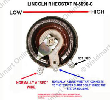
The first step is to check the fine-current control rheostat:
- Turn the knob: it should turn smoothly with no stops or "rough spots." If there is any doubt about the mechanics part of this, remove it and give it a visual inspection.
Then check the resistance (remove one of the wires before testing). It should smoothly measure from 0 to 64 ohms with no breaks or jumps: smoothly up and smoothly down.
The Lincoln® part number for this part is M-5090-C, and it can ordered from Weldmart-Online LLC with a TWO-YEAR WARRANTY!
If the fine-current control rheostat is not defective, the next step is to check the exciter shunt coils.
- From the center terminal, the control arm, there is a blue wire that goes into the stator housing. This wire connects to one side of the welder shunt coils (there are two of them, one on one side of the housing, the other one opposite of the first).
The other side of the welder shunt coil is connected by a brown wire that goes to a terminal on the reed switch, located on the reed switch mounting bar. On this terminal you will find a black wire that is connected directly to the reed switch.
A third wire, black, goes from the reed switch directly to the right, POSITIVE, exciter brush holder.
The whole control circuit is a series connected system. Since this is a simple DC generator with a rheostat to vary the voltage that is applied to the stator shunt coils, this controls the welding current (the heat of the weld).
With the right (POSITIVE) brush removed from its holder -- make sure it is not touching the exciter armature in any way -- take resistance measurements of the system. What this does is tell us if there is an open (broken) circuit. It has been my experience that there are more problems with the exciter system than any other part of the SA-200.
- The engine is not running.
- The current control rheostat is in the “0”, minimum position
- The right (POSITIVE) exciter brush is removed and not touching the exciter armature in any way. If there is any doubt, wrap the brush with tape.
Resistance readings: With the right brush removed from the brush holder, the following readings will tell you certain things.
- With ohmmeter lead on the negative brush holder and the other lead on the center terminal of the fine-current control rheostat, you should read approximately 46 Ohms.
- If your reading is close to 165 Ohms (+/- 10%) you can be fairly sure that there are no "breaks" (opens) in the circuit. This doesn’t mean that there is not a problem with this circuit; it just means that there are no "breaks."
- If the reading is below 165 ohms, you have a winding-to-winding short. Normally the coils will be within specs, or "OPEN," no resistance in the circuit. The coil must be replaced; get more information on Weldmart-Onlinereplacement shunt coils.